25+ transfer function block diagram examples
Can manipulate block diagrams with transfer functions as if they were. Then eliminating two loops results in Figure 3-43b.
2
Step 3 Get the.
. Also the transfer function of a single block is its output-to-input transform. This permits the signal to proceed unaltered along several different paths to several destinations. Solved Example based on the calculation of the overall transfer function of a.
It consists of unidirectional operational blocks that. Block Diagram Reduction Solved Example 1Topics discussed1. Block Diagrams and Transfer Functions From a z-domain block diagram the transfer function can be determined.
Transfer Function Example 1 The impulse response of a system is What will be the transfer function of the system. Three most basic simplifying rules are described in detail as follows. Transfer Function is defined as the relationship between an input signal and an output signal to a device.
Hence b c This system has the same transfer function determined in part a because multiplication of. Yz 2Xz z1Xz 1 2 z1Yz Hz Yz Xz 2z1 1 1 2 z1. Block diagram models The block diagram is a diagrammatic means to represent the cause-and-effect relationship of system variables.
For example the transfer function. Solution For impulse response the output C s of the. Consider the following equations in Transfer Functions Block Diagrams.
Reduce the system to a single transfer function. Project girl Created at. TRANSFER FUNCTIONS AND BLOCK DIAGRAMS 1.
Block Diagram Simplification Example 1 Rearrange the following into a unity -feedback system Move the feedback block 𝐻𝐻𝑠𝑠 forward past the summing junction Add an inverse block on 𝑅𝑅𝑠𝑠to. Tuesday 01st of January 2013 065913 PM Last Edited Or Replied at Tuesday 01st of January 2013. Coefficients of the numerator and denominator polynomials of the transfer function.
Block Diagrams and Transfer Functions - Posted By. Multiplication of transfer functions convolution of impulse responses u u composition y y A B BA ramifications. Simplify the block diagram then obtain the close-loop transfer function C.
First move the branch point of the path involving HI outside the loop involving H as shown in Figure 3-43a. Step 1 Find the transfer function of block diagram by considering one input at a time and make the remaining inputs as zero. Step 2 Repeat step 1 for remaining inputs.
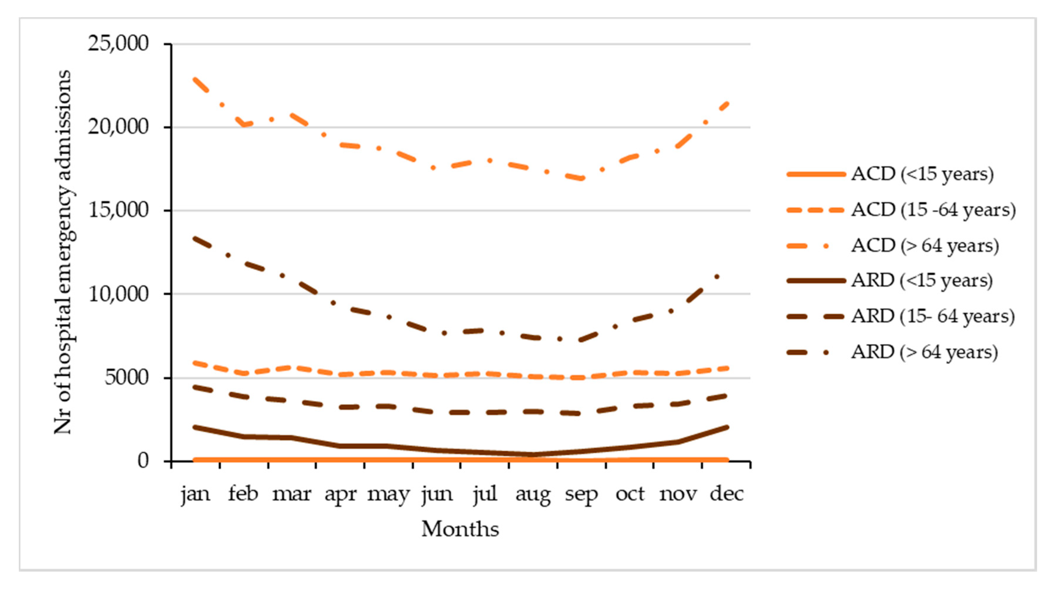
Applied Sciences Free Full Text Air Pollution And Emergency Hospital Admissions Evidences From Lisbon Metropolitan Area Portugal Html

Is A College Education Worth It Weighing The Options For Adult Learners
Solved Find The Error Transfer Function E S R S Of The System Whose Block Diagram Is Given What Should K Be For The Steady State Error To Be Course Hero

Comporium Communications Modernization Of The Enterprise Platform
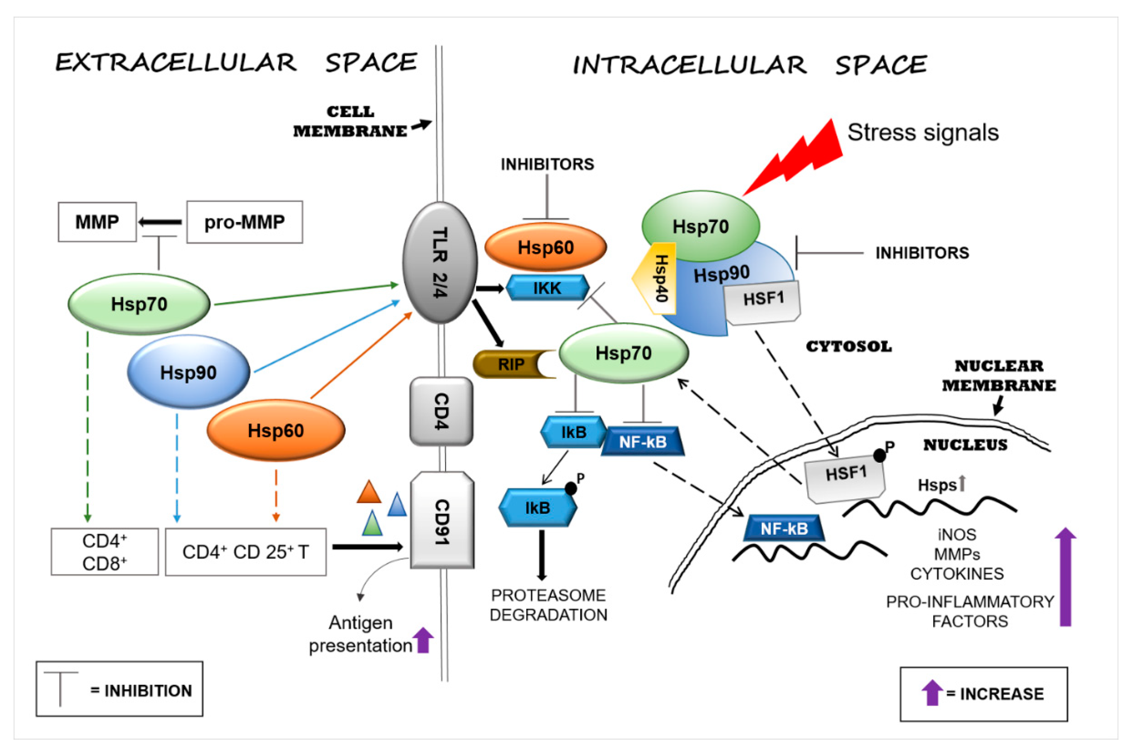
Applied Sciences Free Full Text Functions And Therapeutic Potential Of Extracellular Hsp60 Hsp70 And Hsp90 In Neuroinflammatory Disorders Html

Top 25 Computer Architecture Interview Questions And Answers
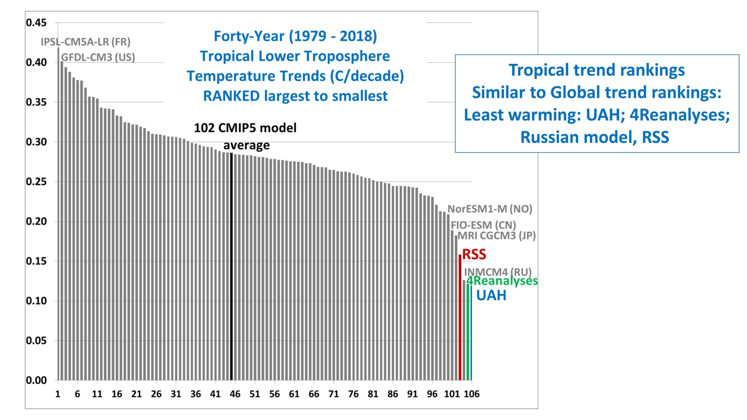
Cmip5 Model Atmospheric Warming 1979 2018 Some Comparisons To Observations Roy Spencer Phd

Applied Sciences Free Full Text Optical Power Budget Of 25 Gbps Im Dd Pon With Digital Signal Post Equalization Html
2

Get 25 Magento 2 Performance Tuning Tips Part 2 Bsscommerce Blog

Tech Media And Communications Software Harris Williams

Get 25 Magento 2 Performance Tuning Tips Part 2 Bsscommerce Blog

Investing Archives Managing Fi
Solved Consider The System Represented By The Block Diagram Of The Following Figure The Closed Loop Transfer Function T S Y S R S Is Select Course Hero

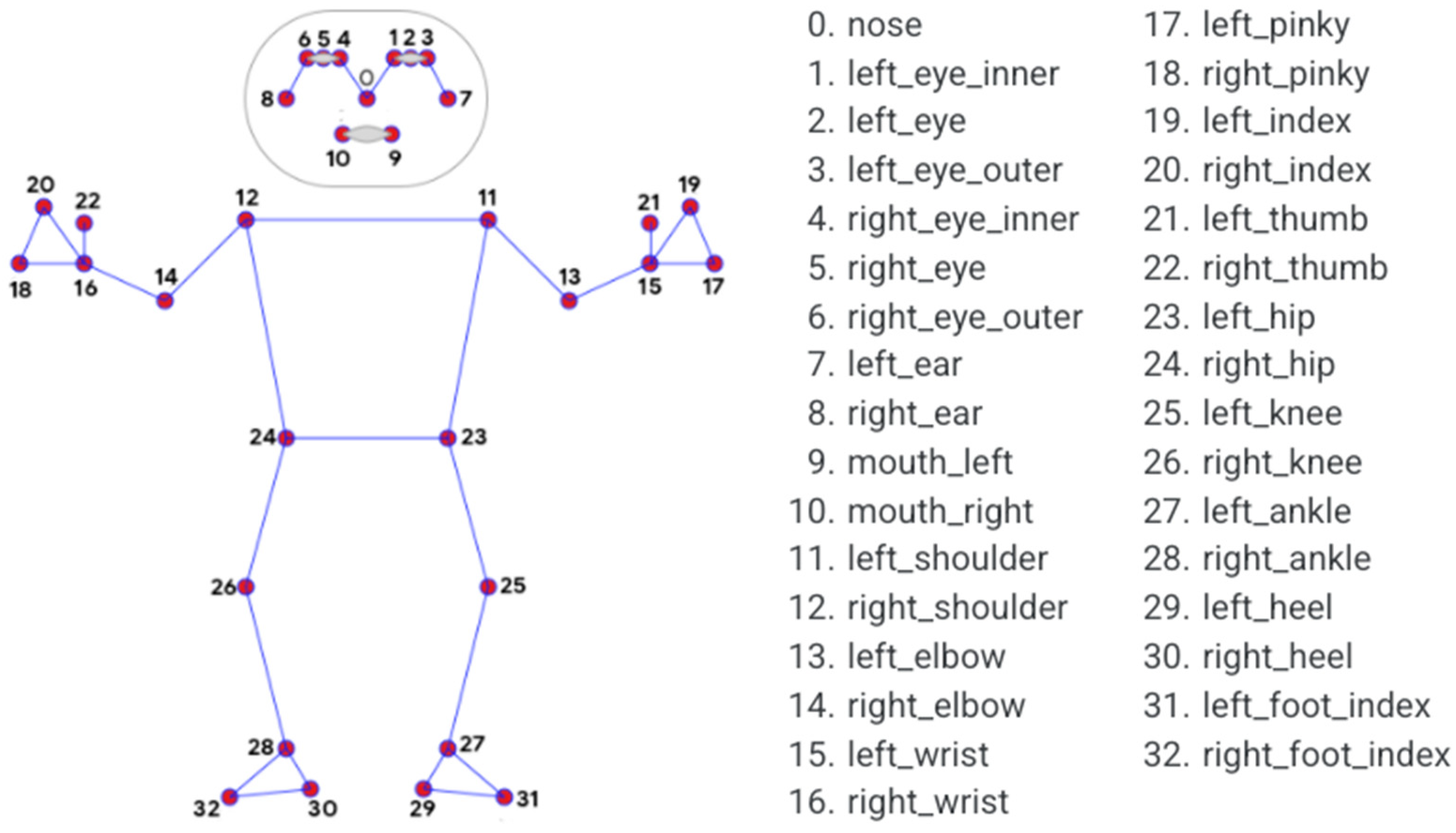
Sensors Free Full Text Fall Detection For Shipboard Seafarers Based On Optimized Blazepose And Lstm Html

Aadi Bioscience Inc 2021 Current Report 8 K
Solved Find The Error Transfer Function E S R S Of The System Whose Block Diagram Is Given What Should K Be For The Steady State Error To Be Course Hero